Since I started building guitars, I’ve heard a lot about “Treble Bleed”. I’ve noticed peples opinions on the subject as split about 45%-45%-10%. 45% says they are essential, 45% say they are awful, and then 10% say they have their place; not essential, not awful. Then there is always someone that throws in “50’s Wiring” as the perfect solution.
Rather than build out a guitar with each version (there are 3 different tone bleed circuits I can find), I decided to do some LTSpice modeling and make some Bode plots. I took a simple single coil type wiring and copied it several times, modifying it each time to model each of the 3 treble bleed circuits and another for the 50s wiring.
Let’s see what’s what..
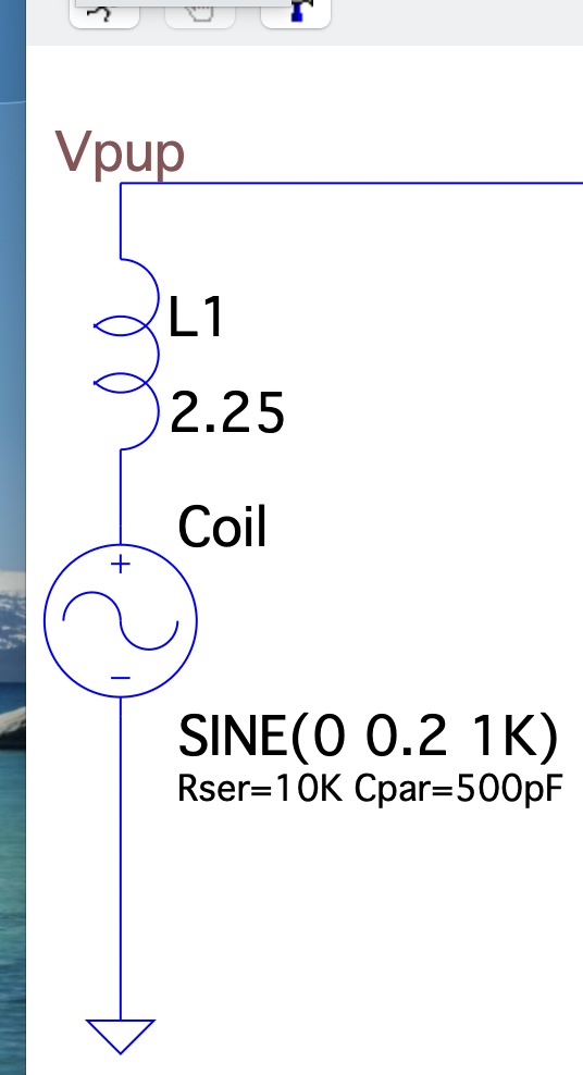
But first, how are we going to model the pickup? A signal source, of course, some DCR (Rser) and some Capacitance (Cpar) as parameters to the LTSpice Signal object. But also add some series Inductance (L1) for the coil itself. The values I used came from various searches on in the internet.
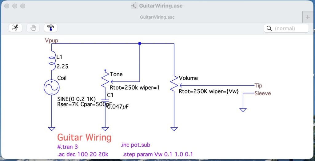
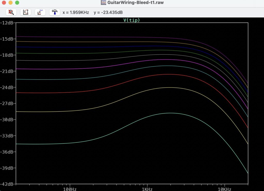
Using this Pickup model, we have the straight forward wiring of a Pup with a Tone Control and a Volume Control1. I am setting the pots to full on2, because that’s how I roll. Think of turning the volume and tone all the way up on the guitar.
Sure, enough, the Bode shows, for at least the sonic range of a Spanish guitar if it had 24 frets (E2 .. E6, or about 83 Hz to 1320 Hz), a flat response plot at all values for the Volume pot.
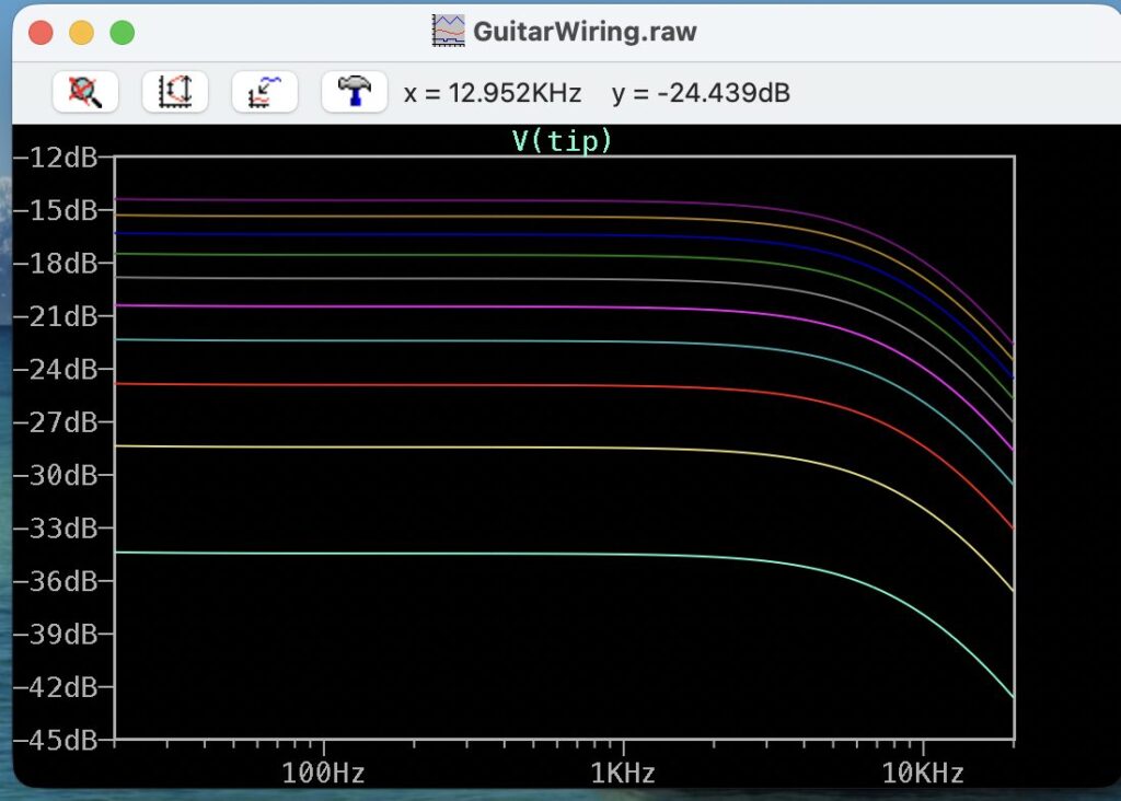
What is not modeled is the frequency response of everything south of the guitar: the amplifier, the speaker, your ear, and the complex waveform and associated harmonics which will extend well above the 1320 Hz and into the roll-off range.. If the response if flat, why bother with a treble bleed circuit? Maybe because our ears, or amps have a natural drop off? No idea. So let’s just trudge ahead and see the affect of the various treble bleed circuits on the Bode plots.
This is the most common bleed circuit; a resistor in parallel with a capacitor.
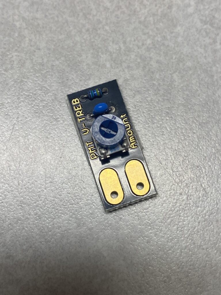
This is a more complex version of a parallel bleed circuit. It has a trim pot so you can adjust the amount of bleed to customize for your tone.
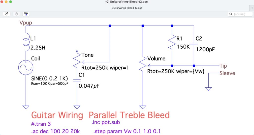
Most of the bleed circuits you find for sale are one of these types and are attached across the input and output of the volume pot. While the component values can vary, most I have seen use a 150K Ω resistor and a 1200pF capacitor. I modified the model to include this parallel bleed circuit
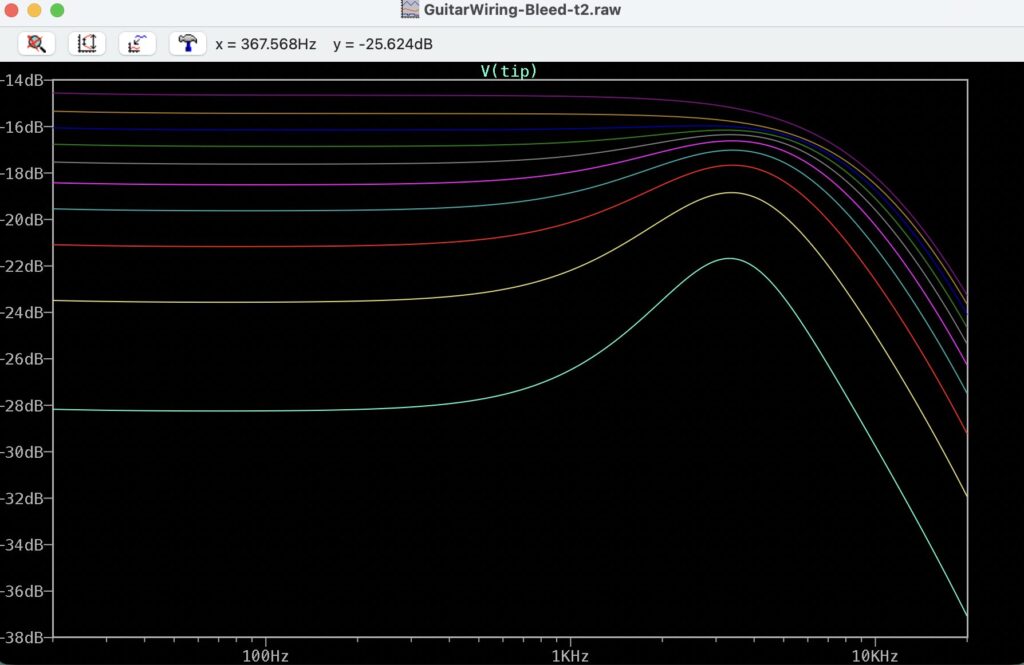
Now we see a bump in the higher frequencies, which is what we expected. The bump even becomes more pronounced as you back off the volume. It’s beginning to sound (look) more like a treble bleed now.
Another way to wire in the bleed circuit is to put the capacitor in series with the resistor.
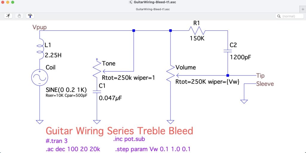
Using the same values for the components provide not as much of a bump on the treble end. It’s a little smoother of a bump, so may not sound as harsh?
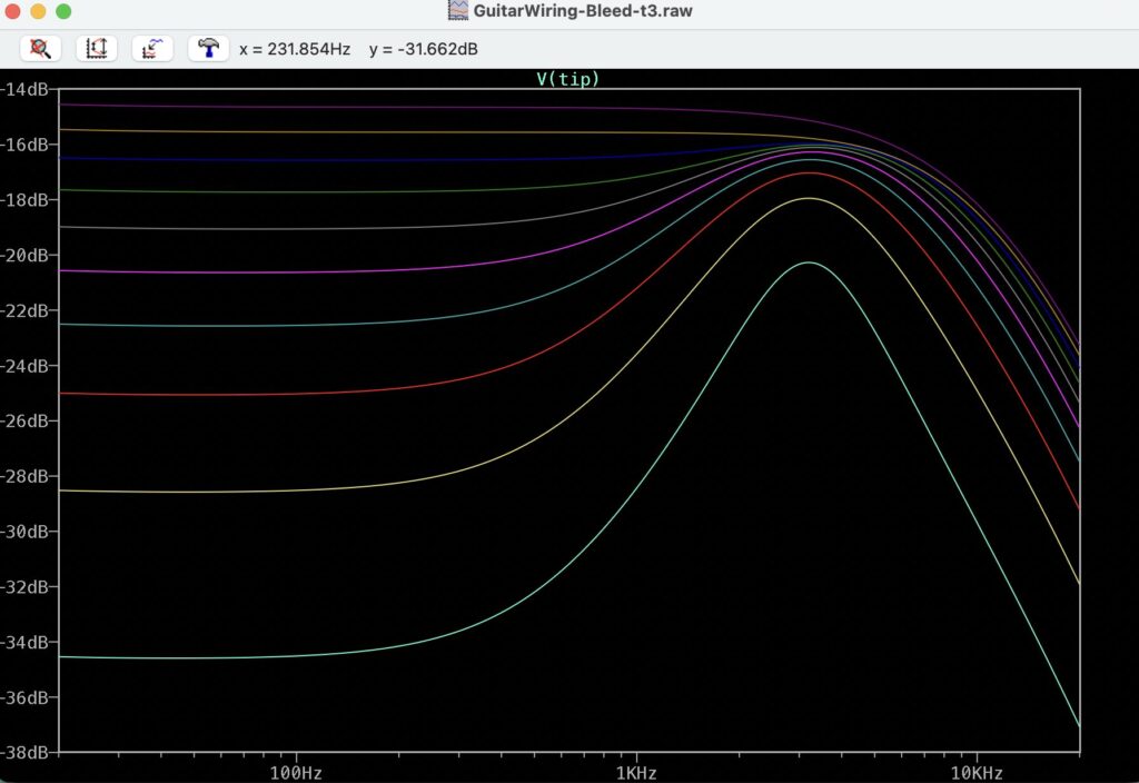
You can also forgo the resistor all together
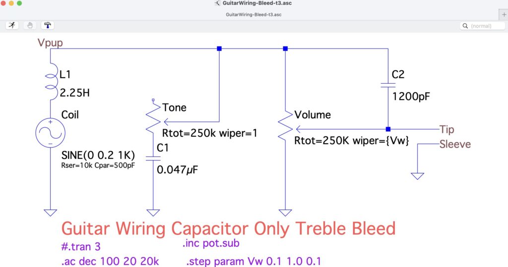
The plot has a much larger bump.
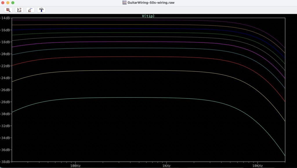
When ever there is a discussion about the pros and cons of a treble bleed circuit, someone always brings up the “50s Wiring”. From what I can tell, basically, the Tone control is not grounded, but is instead sent directly to the output.
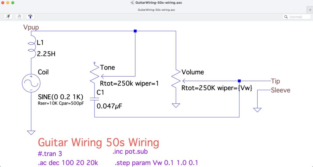
Looking at the Bode plot, it doesn’t seem to be much better than the basic wiring. No bump at all in the treble end.
Maybe I have the circuit wrong?
There are many ways to wire a guitar; 50s wiring, 60s wiring, lots of custom wirings. To be honest I can’t tell, from these plots, which is better than the other, or maybe none at all. I’ll be installing these in future builds and I’ll try the 50s wiring, too.